Exhibition set up
Sunday, 15 June 2014
Tuesday, 3 June 2014
Assessment 5 - Natural forms
A box was made in grasshopper and populated with 3D points
3D Voronoi was used to create blocks within the box
An attractor (NURB) was added so that all blocks points within a certain number (on the slider) would remain and the rest can be hidden
The formation of the blocks can be changed by adjusting the number slider
Once I was satisfied with the form I added a mesh to the form using the Weavebird plugin, which has the ability to thicken the mesh
Final iteration of 3D model
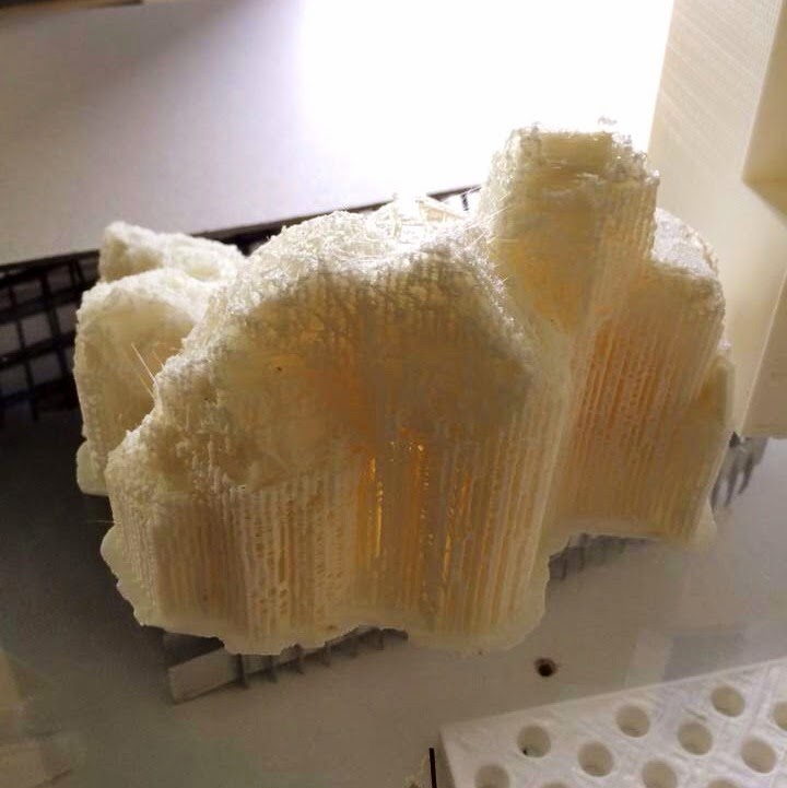
Unfortunately this model is very hard to 3D print, so I decided to print the base form instead and forego the meshes in my real life model.
Rough print of model.
In my first prototype I attempted to print with the mesh pattern on the outside but it did not turn out well.
For my final model I decided to forego the mesh patterning outside and just print the form instead.
Prototype of model once the mesh was removed.
Half of final model (below). The model needed to be split in half in order to fit in the machine (in order to meet the assessment 5 dimensions).
The print was not successful because the machine jammed when the print was up to 60%.
For my final model I decided to forego the mesh patterning outside and just print the form instead.
Other half of final model (above)
Assessment 4 - Joining structure
I created a dodecahedron in grassshopper with the Lunchbox plugin
I separated the faces and edges so that I could work on one face and apply the same step to the other faces
Planes were created on every face
One face was extruded and the edges were divided into 5 segments so that the slots can be made
Rectangular blocks were swept along the edges to create the slots and then were trimmed out from the extruded face
The faces were then oriented and exported for laser cutting
The first attempt at laser cutting the model (below).
Problem encountered: Even though I took the material thickness into account, I didn't think about the angles required for the assembly of the dodecahedron, therefore the slot sizes need to be adjusted.
The final product.
The slot sizes were adjusted and fit together perfectly so that glue was not required.
Tuesday, 29 April 2014
Assessment 3 -Waffling
Three curves were created in rhino and were then lofted in GH.
A bounding box was then linked to the loft and Brep Wireframe created the wireframe of the shape.
The shape was then divided by 10 in both the X and Y directions.
The end points of each direction were culled as they are not needed in the waffling model.
The points were then linked to YZ and XZ planes.
The Brep planes created were then offset by the intended slice width and then a surface was created between each offset line.
These surfaces were then extruded by the intended material thickness in the X and Y directions
The intersection points of the X and Y slices were established using the Curve intersection, cross referenced with the Brep planes from earlier.
A sublist was created to find the domain of the model.
Problem encountered: The Sublist created 1920 items instead of the 81 that were required and caused problems later on. It later was established that the sublist was an unnecessary step and was removed.
Boxes (width of material thickness) were then created at every intersection point (linked to the X and Y planes) and were moved up or down the intersecting points of the slices according to which planes they were on (eg. boxes going in the X plane were moved down and boxes in the Y plane were moved up) .
Once the position of the boxes were established, they were subtracted from the extruded slices using Solid Difference to create the slots.

Brep planes were then created from the solid difference and then oriented them to be ready for lasercutting.
The lines were then baked and exported to illustrator.
Final Script:
Waffling model
Tuesday, 1 April 2014
Assessment 2 - 3D Printing
 | ||
| A circle was made in GH with an adjustable radius. It was then divided into segments and frames were created at each segment |
 |
| The planes were rotated on the Z axis and multiplied by Pi |
 |
| A polygon was made on the path of the circle with adjustable radius and number of faces, and the points were lofted to create a solid shape |
 |
| The faces were then exploded, listed individually and reparameterized to the new U,V axes. The points on each face were then evaluated to an attractor point. |
 |
| The cone was then applied to each point and its length was relative to the attractor point |
 |
| Final Script |
The model was then baked into Rhino and was cut in half so that the printing process will be easier
Attempt 1: Model stopped about 1/4 way up (reason unknown)
Attempt 2: One half printed well but other half seemed to be hollow
(possibly was not capped properly?)
Final model
Subscribe to:
Comments (Atom)


